The Essential Microcontroller
Instructions for building the RS232 Controller/Trainer
First make sure you have all of the component parts. Purchase them from Digikey.
You must already be skilled in soldering, or know someone who is, and be willing to learn from them.
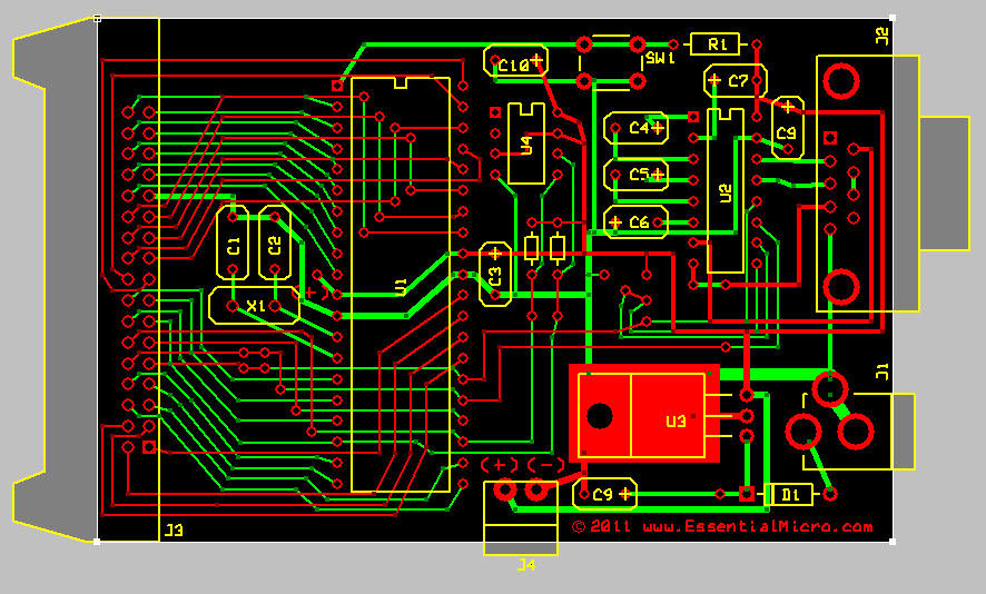
Locate the components in the above figure and place components in the appropriate matching holes, on the component side of the board as shown. Solder the components from the bottom of the board.
After all components have been soldered in, remove excess flux using an appropriate solvent.
Note that the U4 socket is for an optional serial EEPROM for experimenting with the I2C interface.
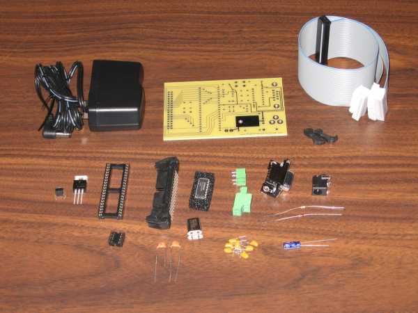
The above photo shows all the parts needed to complete the Kit before assembly.
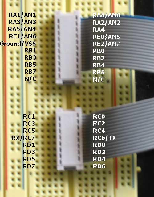
The above photo shows the cable pinout at the DIP connectors. The text version is also available.
Note: RC6 and RC7 are the TX and RX pins used for serial communication. It is not recommended to use these pins. Therefore, it is suggested that you can modify the board to send supply or other signals via these connections. All boards manufactured after 2010 have two jumpers located near X1 which could be used to accommodate this modification.